
Blog
Plastic Injection Molding Design Tips
6 Do's and Dont's from the Experts
August 7, 2018
When designing a product, it’s easy to create something that fits all requirements for the product's intent without any thought about the manufacturing process. Many times, it might not be clear what manufacturing process will be used to produce the final product.
At Cadrex, we are experts in working with plastic injection molding manufacturers. We understand the complications that come with adjusting a design to complement the injection molding manufacturing process. Our Design for Manufacturability (DFM) engineers have decades of experience helping customers make modifications to their designs to ensure their product is manufacturable, cost-conscious, can meet geometric tolerances, and works with the chosen material without compromising the integrity and functionality of the product.
*engineering tip: .step files are the best choice when sharing design files
We have put together 6 design tips to help engineers with designing for injection molding.
Tip 1: Do not design a part with non-uniform nominal wall thickness
- Varying wall thickness creates uneven fill throughout the cavity
- Thinner sections will cool faster than thicker areas causing highly stressed areas where distortion and warping will occur
- It is recommended to core out the thick areas to create uniform walls, which will reduce cycle time and plastic usage and improve part cosmetics
- Depending on the type of material being used, nominal wall thickness should not vary more than 15%
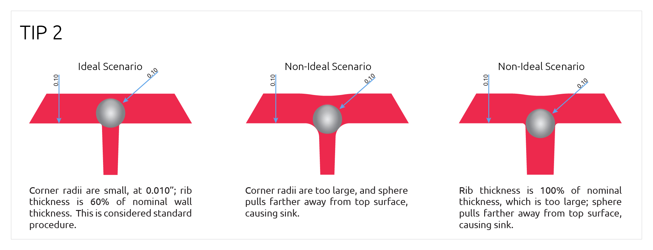
Tip 2: Do identify possible sink areas and design them out
- Sink areas are likely to occur at intersections of a rib and nominal wall where proper design guidelines are not followed
- Rule of thumb: Ribs should be a maximum of 70% of nominal wall, but 60% is preferred
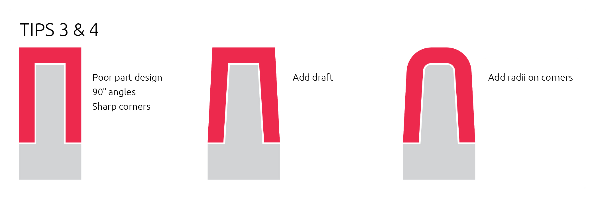
Tip 3: Do create radii on all corners
*note: too large of radii on ribs cause sink
- Sharp inside corners become stressed and outside corners are difficult to fill and trap air
- Avoid radii on parting line – causes excess expense on tool build
- Adding radii improves fill of corners and distributes stress across a larger area
- .030" radius minimum if possible and if radii are less than .010" they are not worth adding to design
- Place radii at the end of design tree to make collaboration with DFM engineers easier
Tip 4: Do allow at least 1° draft for part release
- For textured surface, more draft is required – follow texture guidelines
- If possible, more than 1° draft is better
- 3° draft or more is needed when parting line transitions from one level to another
- Less than 3° draft causes the steel to squeeze together when mold closes making the mold harder to pull apart and creating drag marks on the part
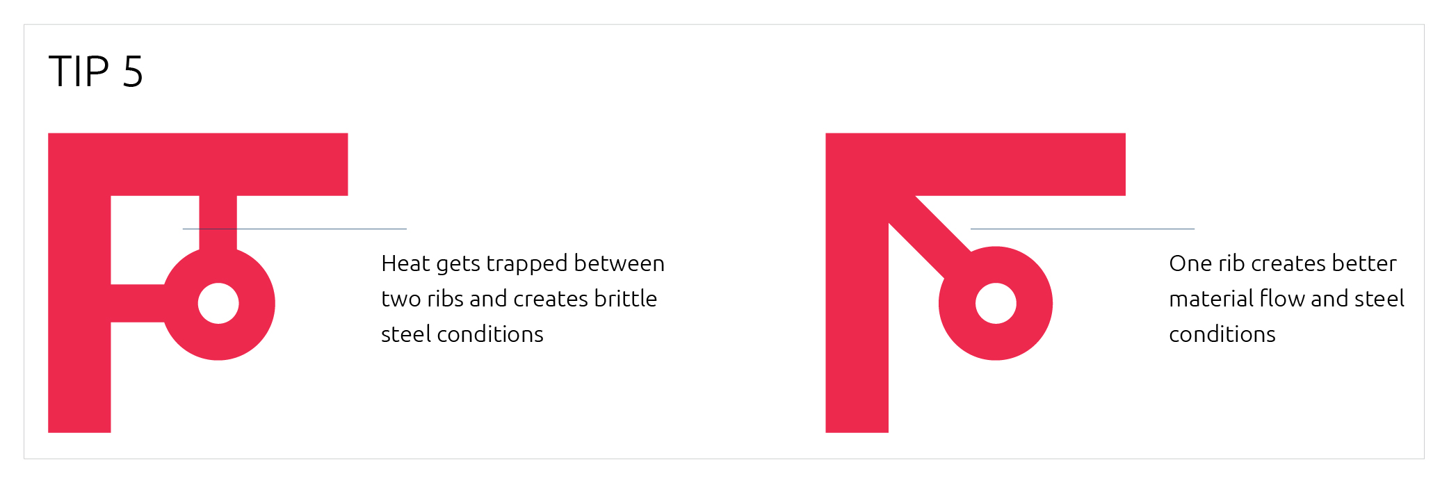
Tip 5: Do not design bad steel conditions
- When envisioning steel required to create part shape, avoid very sharp, tall, and fragile steel conditions
- Steel will get hot and be brittle
- Steel condition height should not be more than 4x the width whenever possible
- When in a corner, one rib is better than two to allow the steel to cool better
Tip 6: Do not design deep ribs with square corners
- It will trap gas and cause short shots
- It will be more difficult to eject part
Recent Insights
News
Blog
White Papers