
Introduction
Thinking about sheet metal fabrication may conjure images of the Industrial Revolution, a time when machines became synonymous with manufacturing, leading to the widespread growth of efficient production processes. However, the practice of transforming sheet metal into specific shapes dates back much further; ancient metalworkers used the process to create jewelry. Now, precision sheet metal fabrication is used to create everything from data centers to electric vehicle charging stations. It is the basis for the infrastructure that keeps our world running.
Materials used in sheet metal fabrication are strong and resistant to corrosion, making them ideal for use in industries like aerospace and defense, renewable energy, electrical infrastructure, and kiosk manufacturing. The versatility of sheet metal allows for its use in large sheet metal enclosures like data centers and battery storage containers and smaller assemblies like kiosks and vending machines. From the depths of the ocean to outer space or your home office, products made by sheet metal fabrication are found everywhere.
Sheet Metal Fabrication Defined
Sheet metal fabrication is the process of transforming flat sheets of metal into specific shapes using a variety of forming, punching, cutting, and assembly methods. This manufacturing process offers a high degree of design flexibility; metal sheets of various gauges can be manipulated into nearly any shape or size. Sheet metal is an ideal manufacturing material because it is malleable, strong, and durable.
Primary Methods of Sheet Metal Fabrication
The primary methods are metal fabrication and metal stamping. Metal fabrication, also known as soft tooling, uses lasers, turrets, and brake presses to manipulate a piece of metal into a specific shape or size. Soft tooling allows a product to hit the ground running with minimal to zero tooling investment. It also allows for flexibility during a product's design, prototype, and production ramp. This process does not involve adding material to the workpiece to achieve the desired shape.
Metal stamping, also known as hard tooling, is a process in which flat or coiled sheet metal is fed into a stamping press where a tool and die surface transforms the material into precisely shaped parts. This method is commonly used to create a high volume of parts with precision and repeated results. Parts are produced much quicker and require less labor, which can be highly beneficial as a product becomes a staple in the market and demand increases.
Many sheet metal assemblies are a mix of soft- and hard-tool parts.
Common Sheet Metal Terms
Assembly - the action of putting together individual or partially assembled units to build a complete product. Base metal - the sheet of metal that is to be cut, bent, or punched.
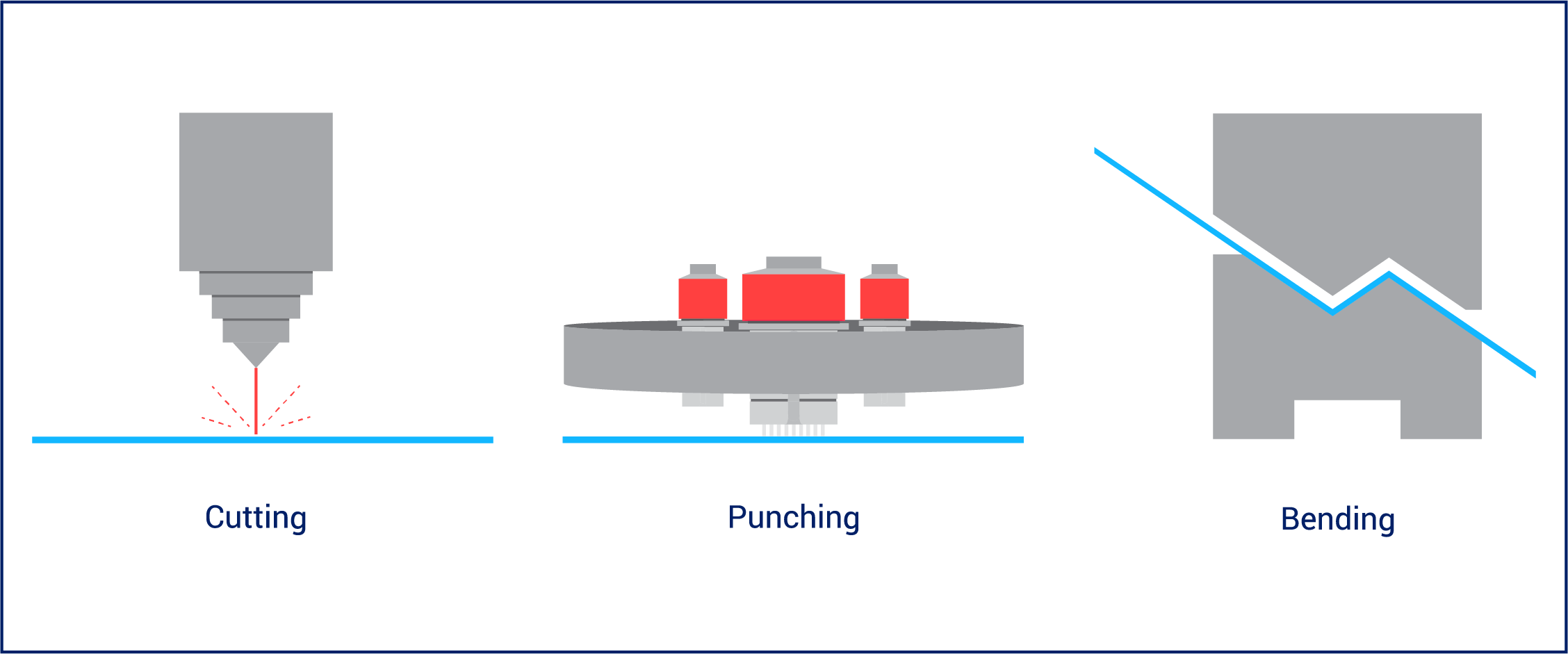
Bending - the process of applying pressure to specific areas of the base sheet of metal to achieve a desired shape.
Blanking - the process of removing a piece in a desired shape from the base sheet of metal and discarding the remaining metal around it, like using a cookie cutter. Blanking typically occurs prior to bending but can happen while forming, depending on the machine.
CAD - computer-aided design; engineers use CAD software to design 2D and 3D models.
Coining - a forming process that uses pressure to mold a workpiece to the shape of a die.
Cutting - the use of blades, torches, or lasers to remove pieces of sheet metal.
Die - in soft tool, the lower part of a tool & die set that sits below the material; used to cut, shape, or form the material. In hard tool the die is the entire tool.
Embossing - a process that involves raising one side of the material while the other is depressed.
Forming - the process of cutting, punching, or bending sheet metal to create a desired shape.
Hard tooling - also known as sheet metal stamping, tools are made of more durable materials, making it ideal for large quantities of parts.
Hardware installation - the installation of hardware to allow for assembly includes nuts, studs, & standoffs.
Lancing - when a slice or slit is made in a piece of metal without causing separation from the main piece.
Laser cutting - an extremely precise cutting method that uses a concentrated beam of light. Also used by evil geniuses.
Machining/milling - the controlled removal of material using a cutting tool or lathe.
Nesting - strategically fitting multiple parts on a single sheet of metal to reduce waste; commonly arranged automatically by nesting software.
Plasma cutting - the use of concentrated ionized gas, or plasma, to melt away portions of sheet metal.
Powder coating - a dry powder surface coating applied to final metal pieces; when heated, it bonds with the metal to ensure a lasting finish and color.
Press brake - a machine that forms predetermined angles, or bends, by squeezing a sheet of metal between a matching punch and a die.
Punch - the upper part of a tool and die set that uses compression to cut, shape, or form the material.
Punch press - a machine that uses mechanical force and a die set to cut, pierce, or form a sheet of metal.
Riveting - the installation of a mechanical fastener, or rivet, through a hole in the material to hold two or more pieces of sheet metal together.
Set-up time - the time it takes to set up a machine, tool, or process. This time varies depending on the complexity of the part, machine, and process.
Shearing - a form of cutting in which downward force is applied to a piece of sheet metal, creating a clean break.
Soft tooling - the sheet metal fabrication processes that include laser cutting, turret punches, and press brake forming; a more cost-effective method than hard tooling because of its design & material flexibility
Stamping - accomplished using steel dies - progressive and stage - that are designed to stamp, bend, and form sheet metal.
Tooling - the equipment needed to carry out a particular function in the manufacturing process.
Tonnage - The amount of force applied by a press.
Turret - a type of punch press that uses turrets, or rotating tool holders, to punch sheet metal.
Welding - a process that involves melting or soldering two or more pieces of metal to join them together.
Workpiece - the material transformed into a finished part or component through manufacturing processes.
Common Materials
Many different types of metal or metal alloys can be used in sheet metal fabrication, and designers will analyze several factors to determine the best fit for a project. The cost, durability, and weight of a material factor into the decision.
Some of the most common materials used in sheet metal fabrication include aluminum, brass, bronze, copper, nickel, steel, and tin. These metals and alloys are used for their varying levels of malleability, resistance to corrosion, and strength.
To learn more about sheet metal fabrication materials, read our Materials Handbook.
Types of Sheet Metal Fabrication Machines
Press Brake
A press brake squeezes a sheet of metal between a punch and a die to bend it to predefined specifications. The material type, gauge, and geometry of the bend determine the tonnage, or force, needed to bend the metal. Standard punches and dies produce simple bends based on straightforward geometry, whereas custom punches and dies are created to implement more complex bends. Custom punches and dies do not lend themselves well to automated forming machines, and they may be better suited for automatic tool changers or robots.
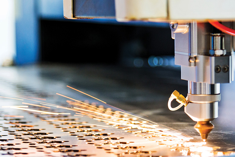
Laser Cutter
Laser cutters use a laser to cut through sheet metal. The sheet is placed into the machine, and the laser cutting head is programmed to move along a desired cutting path. Laser cutting offers geometrical flexibility because the cut options are not limited to a standard tool. Some lasers have a stationary bed, but others move the sheet to its necessary position.
Turret Press
A turret press, also known as a turret punch, holds a variety of standard tools to punch shapes out of sheet metal. The sheet is laid flat and clamped into the turret. The machine is programmed to move the sheet metal across the machine bed and make a series of punches to achieve the desired part. Some machine models have a rotating turret, which holds a variety of tools and rotates to bring a specific tool into punching position. Others store their tools on a rail system, and the machine retrieves the needed tool.
Metal Stamping Press
Metal stamping is excellent for producing multiple, uniform metal parts at scale. Blank or coiled sheet metal is fed into a press, where it is shaped by a tool and die. Common operations are embossing, blanking, coining, punching, and flanging.
Types of Metal Stamping dies
Progressive Dies
A progressive die performs sequential operations on a piece of sheet metal. As the press moves, the metal advances through the machine one station at a time. The final station cuts the completed piece free from the strip of metal. The finished pieces and excess metal are automatically separated.
Stage Dies
Unlike progressive dies, a stage die works on one part at a time. The metal sheet is moved in and out of the die either by a human operator or through a robotic process. Stage die types include compound, pierce, forming, ratchet, and coining.
Sheet Metal Joining Methods
Sheet metal fabrication isn't just about cutting and bending. In many cases, multiple metal parts need to be combined. Welding and riveting are the two most common assembly options for sheet metal. The end use of the product should be considered when determining which method to use.

Welding
Welding is the most expensive joining method, but it is often the only viable process in areas that do not allow for overlap or assembly holes. It is also used in applications where strength and rigidity are critical. Because the heat produced by welding has a direct effect on metal quality, as a rule, heat should be minimized whenever possible
MIG - MIG stands for "metal inert gas" and is commonly referred to as wire-feed welding. MIG creates an electric arc between a piece of wire and the metal it touches, causing both to melt and join. It is best used on strong, thick materials that will not succumb to massive heat distortion.
TIG - TIG stands for "tungsten inert gas." This method is commonly used to weld stainless steel or aluminum. TIG welding is best used on thinner materials because it is easier to control the heat. It is more expensive than MIG welding because it is a slower, more labor-intensive process, but it is ideal for minimizing distortion.
Laser - Laser welding uses a laser beam to create a highly concentrated heat source to join pieces of metal together. This method allows an operator to target a precise area of a workpiece with a laser beam, which then heats, melts, and fuses the material. This process is frequently used in sheet metal fabrication when manufacturing a high volume of precision parts.
Spot - Two pieces of metal are placed under pressure between two copper alloy tips, which apply an electrical current, welding the pieces together. Welds are flush to the surface, and no fluxes or fillers are required, allowing for a clean appearance.
Robotic - Robotic welding is an automated process. Most robots are used for laser welding, resistance spot welding and arc welding. Human operators typically perform MIG and TIG welding; however, if a robot performs MIG or TIG welding, human assistance is required to prepare the welding materials.
Riveting
Rivets are used to fasten two or more pieces of metal together using a manual or powered rivet tool. They are typically made of steel, stainless steel, or aluminum. Riveting has advantages over welding, including the ability to fasten dissimilar materials together or to fasten areas that are not accessible to other processes.
There are three basic types of rivets:
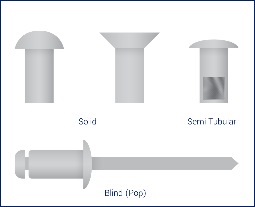
Solid Rivets - Solid rivets consist of a shaft and a head that becomes deformed during insertion. They are inserted using a special rivet machine or a standard hardware insertion machine. Solid rivets are very strong, but they require access to both sides of the sheet metal and an overlapping joint.
Semi-tubular Rivets - Semi-tubular rivets are similar to solid rivets; however, they have a partial hole at the tip. This small hole reduces the amount of force required to install the rivet. Like a solid rivet, access to both sides of the sheet metal and an overlapping joint are required.
Blind Rivets - Blind rivets are used when you can only see or access one side of the sheet metal. They have a cylindrical piece running through them called a mandrel. When the rivet gun pulls the mandrel, the rivet collapses on itself, securing the materials together.
Design Process
Before the manufacturing process begins, engineers analyze the final product's function, aesthetic, and purpose. Mechanical engineers design the product and create the geometry of the part to determine the best tolerances and materials for production.
Manufacturing engineers determine the ideal machines, tools, and equipment for the production and assembly process. Designs are tested during the prototype phase to ensure the manufacturing process runs smoothly.
Design for Manufacturability
Design for manufacturability (DFM) involves reviewing product designs to ensure the final assemblies meet the desired outcome and can be manufactured in the most efficient way. Design for excellence (DFX) is an in-depth review of the entire product and its supply chain. The "X" is for excellence, which is a variable that can have many possible values, including assembly, cost, manufacturability, and time. DFX is an extension of DFM; it includes a broader view of the necessary components of manufacturing because manufacturability is only part of the picture.
Manufacturing experts must be well-versed in the production of a product, including engineering, machines, assembly, automation, quality, and supply chain, to provide the customer with valuable DFM and DFX. They review customer parts at the front end of the process to ensure the final assemblies meet the desired outcome. It is their responsibility to ensure parts are manufacturable, cost-conscious, and can seamlessly move into production, assembly, and testing.
Excessive Forming - Incorporating cuts or bends that do not have a functional purpose can create added costs. Excessive forming can also make the part impossible to bend.
Critical Dimensions - Some call-out information is not available in the CAD file and must be added to the drawings: datum planes, tolerances (block and critical), material type, finish requirements, hardware specifications, hole tapping, welding requirements, surface requirements, and edge requirements.
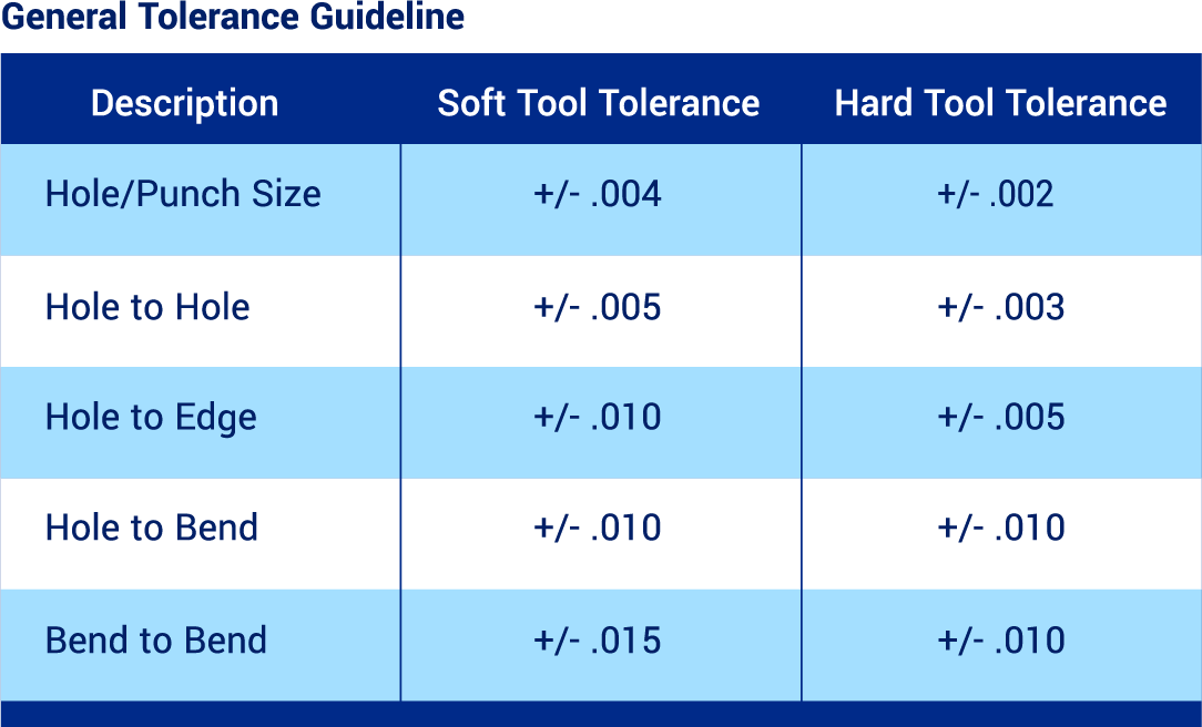
Standard Tolerances - Determining standard tolerances for sheet metal fabrication can be a complex process, particularly because the thickness of the raw material or sheet stock can vary. Manufacturing processes also impact tolerances because different machines have unique tolerance capabilities. Although machinery and tooling can repeat within .004", it is a mistake to simply engineer all mating parts to be within +/-.005" as it can lead to additional labor in sorting and inspection. Tolerances that are too tight result in higher costs and lower productivity. However, correct tolerances will still produce excellent fit and function, with the added benefit of manufacturing efficiency.
Hole Size - The size and shape of the punch and die tooling determine the size and shape of the hole placed in the sheet metal. The thickness of the stock material determines the minimum hole size.
For best results, the punched feature can be no less than the material being punched. The die tool is slightly larger than the punch to minimize tooling wear and reduce the pressure required to punch the hole. Generally speaking, 10% of the material thickness is used for most applications.
For example, if the material is .100" aluminum and the punch diameter is 1.000", the die diameter would be 1.010". The size of the hole on the punch side will be the same size as the punch tool. The size of the hole on the die side will be the same size as the die tool. Except for tooling wear, there is very little variation from one hole to the next. Generally speaking, +/-.003" is a reasonable and functional tolerance.
Hole to Hole - The accuracy of the distance from one hole to another primarily depends on the machinery used to process the sheet. Some equipment will hold better than +/-.005" with little difficulty. All holes and features punched through the sheet can cause stress. If the part has a closely spaced perforated pattern or has formed features such as dimples or counter sinks, the result can cause the sheet to warp and distort. This may lead to unwanted variation between holes or features. A greater tolerance should be applied to certain areas if this condition exists.
Hole to Edge - Part profiles are punched just like any other feature, except when using a machine with shearing capabilities. These dimensions should be considered the same as hole-to-hole. When punching close to an edge (less than double the material thickness), the edge can be pushed out by the stress of punching the metal. This edge movement can introduce variables in the accuracy of the hole location in relation to the edge. There are techniques to minimize this problem, but whenever possible, engineers should allow a +/-.010" hole-to-edge tolerance.
Hole to Bend - Several factors have been introduced leading up to the forming stage of the process. Press brakes will position and repeat within the +/- .002" range. Skilled brake operators can load the parts to form consistently from bend to bend. Nevertheless, consideration must be given to the natural variation in material thickness, (5% of nominal thickness), the +/-.005" from the turret press, the effects of cosmetic sanding, and the variation introduced by the press brake. A tolerance of +/-.010" hole-to-bend is functionally reasonable for most applications.
Bend to Bend - In addition to the variables that affect hole-to-bend tolerances, bend-to-bend tolerances are also impacted by introducing multiple material surfaces and thicknesses. Whenever possible, engineers should allow +/-.015" bend-to-bend. Increased tolerances need to be applied if going across multiple bends.
Concept and Development
Once engineers have a design ready, it's time to make it a reality in the concept and development phase.
Prototyping
Every part is evaluated during the prototype phase to ensure a smooth and speedy production process. These test runs allow engineers to troubleshoot and find solutions to any issues that arise before a product moves to production. During this phase, technical experts and engineers collaborate with customers to ensure the final prototypes function as intended.
New Product Introduction
New Product Introduction (NPI) is the process of developing a product from the first working prototype and bringing it to market. Once a prototype is created, engineers validate the design, and the product is then manufactured and evaluated. The goals of the NPI process are to avoid miscommunication, to produce a product with speed to scale, to save money, and to ensure that production meets quality standards.
EVT (Engineering Validation Test) - EVT refers to the earliest testing runs to ensure the manufactured product meets the customer's specified engineering and functional requirements.
DVT (Design Validation Test) - DVT encompasses the runs that ensure the cosmetics and durability of the final product are correctly met and within the margin of acceptable variance. The DVT stage may include various environmental tests to simulate exposure.
PVT (Production Validation Test) - PVT is the final step before full-scale production, which includes optimizing the production line and determining mechanisms to maintain quality at scale. These testing runs are typically larger and included in the first shipment to customers if the quality criteria are met.
Sheet Metal Fabrication Automation
Both human labor and automation are used in sheet metal fabrication. Automating sheet metal fabrication operations can speed up production, provide better efficiencies, and improve safety conditions. Incorporating automation negates human error and fatigue; operators use it as a tool to enhance the manufacturing process.
Robotic Machine Operators
A robotic operator is programmed to perform specific duties or to move a part or material according to set specifications. If a press brake has a robotic operator, for example, the robot is programmed to move sheet metal across the press brake to achieve each desired bend in the program.
Robotic operations improve productivity as well as quality. Robotic operators can perform with uniform precision every time, reducing potential ergonomic and safety hazards to human operators. For example, some programs require extremely repetitive motion that can injure a person over time. Robotic operators eliminate that risk.
Automated equipment or robots can quickly be reprogrammed to accommodate last-minute engineering changes, small batch runs, and line changeovers.
Collaborative Robotic Arms
Robotic arms do not communicate with a machine and are programmed separately. They work well for pick-and-place operations, where they are programmed to move parts from one location to another. These robots are often paired with a human counterpart, making them collaborative.
Fully Automated Machines
Machine manufacturers are now incorporating automation and robots directly into their technology. These machines are built specifically to perform duties based on specific programming. A good example of this would be a panel bender, which has robotics built into the machine itself to move material through the forming process and into subsequent stages, storage, or racking. This machine is not built to be operated by a human and is fully autonomous by design.
Automatic Tool Changers
Automatic tool changers (ATCs) remove and replace tools in a machine upon command. The manual set-up time for a press brake can take up to four hours depending on the number of bends, but ATCs take up to 30 minutes to set up, no matter how complex the program is. Whether working with press brakes or turrets, ATCs are accurate, fast, and reliable.
Material Load/Unload Systems
Automated sheet loading and unloading systems can be purchased for many machines, including turret and laser combos. This allows the fabrication process to continue seamlessly without needing to have an operator manually feed sheet metal onto the turret. This reduces potential ergonomic hazards and increases productivity.
Advantages of Sheet Metal Fabrication
Sheet metal fabrication is a cost-effective method to produce strong and versatile products. It is an ideal way to create items that need to last with precision and efficiency.
Strength and Durability
Sheet metal is strong and durable, yet malleable; it can be bent, shaped, and formed while maintaining its strength. Products made from sheet metal fabrication are typically resistant to corrosion and able to withstand greater pressure and heat than products made from other materials.
Recyclability
Sheet metal is recyclable, and it often can be remolded into something else while maintaining its natural properties. Both stainless steel and aluminum, for example, are 100 percent recyclable. Recycling sheet metal saves energy from having to produce new products from scratch. Nesting software allows engineers to design programs for machines that create the least amount of waste.
Cost-Effectiveness
Sheet metal fabrication can be more cost-effective than other manufacturing processes. Many of the materials used in sheet metal fabrication are widely available. Engineers who are well-versed in DFM and DFX will ensure product designs can be efficiently manufactured at scale and are economical.
Fabricating the Future
Sheet metal fabrication is a modern-day method that built upon manufacturing processes of the past. Today, expert crafters use state-of-the-art equipment to morph simple pieces of sheet metal into complex products. As automation and technology continue to shape the manufacturing industry, the use of sheet metal fabrication is expected to grow — alongside the demand for strong, long-lasting products made from recyclable materials. Sheet metal fabrication remains one of the most cost-effective methods to produce and assemble large quantities of a single product, with precise and repeated results.
About Cadrex
Cadrex is one of the largest manufacturing partners in North America, with 20 facilities located in nine states and Mexico. As a leading custom mechanical solutions provider for the most innovative companies in the world today, we offer a unique breadth of capabilities and technical expertise that allow us to rapidly bring customer programs from concept to scale. In addition, our decades of specialized experience designing and manufacturing for information communication technology, warehouse automation & robotics, kiosk & gaming, aerospace & defense, renewable energy & electrical infrastructure, and medical sectors make us a trusted partner in our customer's supply chain.
Recent Case Studies
Case Study
Example Case Study Title
Excerpt.....
Case Study
Example Case Study Title
Excerpt.....
Case Study
Example Case Study Title
Excerpt.....