
Introduction
It is easy to brush over the basics of plastic injection molding and start talking about the benefits, especially when you have been working in manufacturing as long as we have. We have put together a list of injection molding definitions to serve as your handy guide when discussing your next project with a contract manufacturer.
Plastic Injection Molding Definition
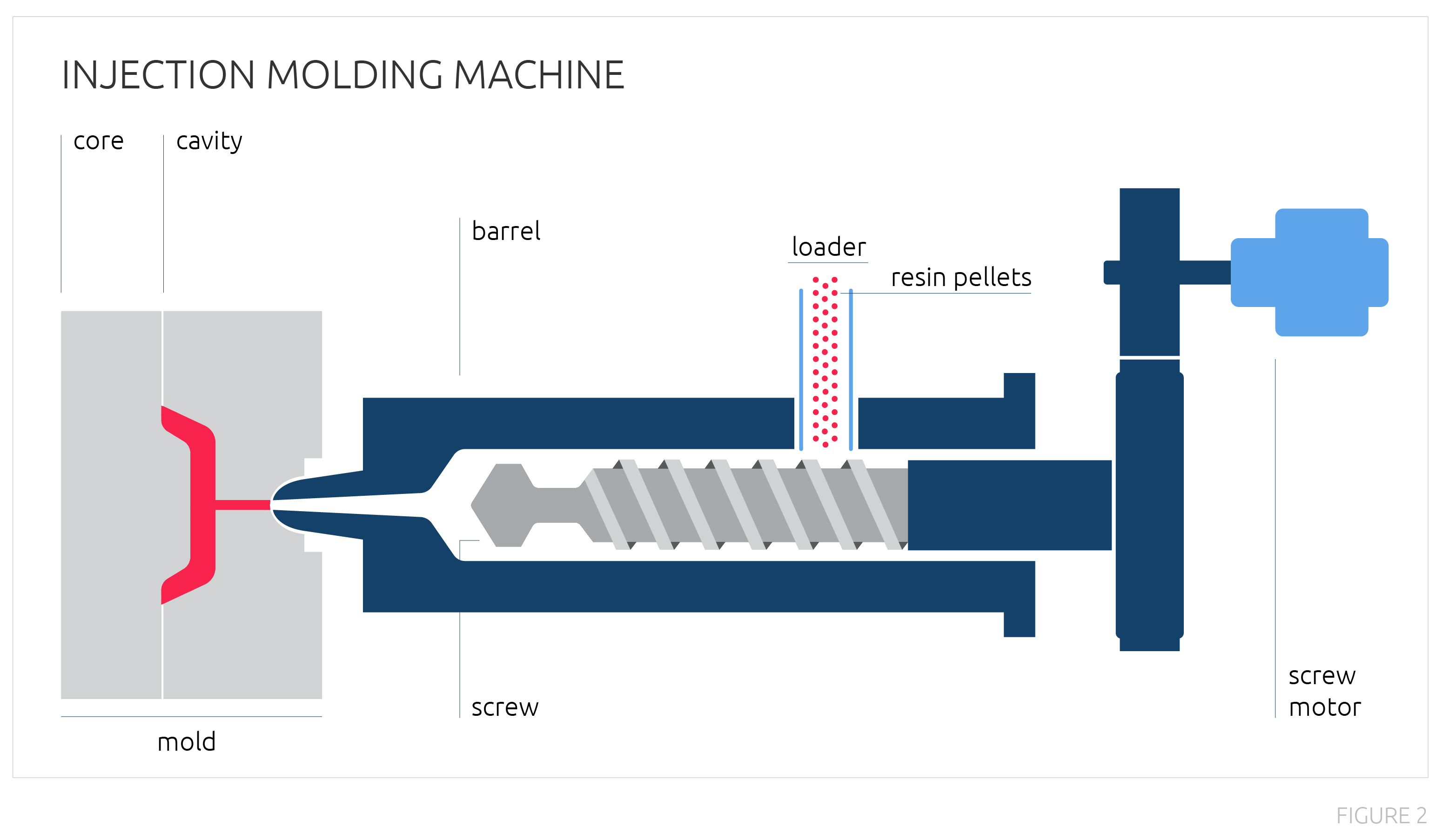
Plastic injection molding is the process of injecting molten plastic material into a metal tool which then cools and ejects a plastic part from the machine. Plastic resin is fed into the loader in pellet form. The material is rotated forward by the screw and makes contact with the heated barrel. Friction and the heated barrel melt the plastic, which accumulates in front of the screw. The machine is programmed to turn off the screw motor when enough material is available. The screw is then used to push material out through the nozzle and into the mold.
With the assistance of cooling channels, the material cools and hardens in the mold. The mold opens after a predetermined cycle time, the plastic part is ejected, and the process is repeated.
Glossary
Barrel- machine component where resin is fed into for heating and mixing; contains the screw
Cavity- hollow half of the mold; typically referenced as the A-side
Clamping Force- force needed to keep mold closed while mold fills with plastic
Cold Runner- channels in the mold that flow material to the part cavity; hardens with part and is removed after ejection
Cooling Channels- channels built throughout the mold to control the mold temperature
Core- half of the mold that fills the hollow side; typically referenced as the B-side
Cycle Time- time it takes to complete one molded part; commonly measured from mold open to next mold open
Ejector Pins- installed in the mold to eject the part from the mold when properly cooled
Flash- excess material on molded par
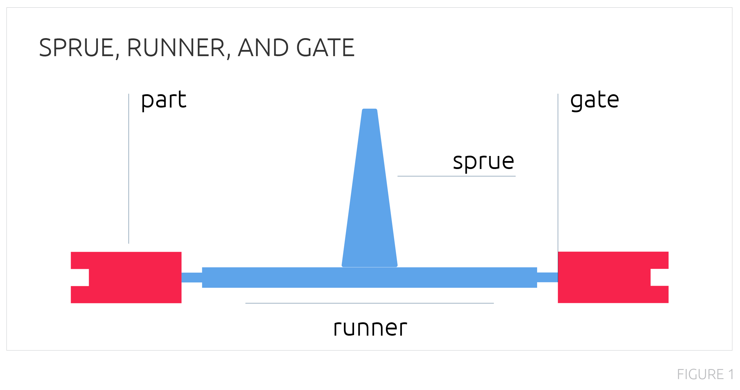
Gate- entry point for plastic into part cavity
Hot Manifold- channel system that runs material to the part cavity and keeps material heated to avoid a runner
Knit Line- occurs where different flow fronts of material meet while flowing through the mold
Mold Flow Analysis- computer simulation of predicted material flow, fill, and warp in mold to assist in tool and part design
Mold (Tool)- made of two halves (core and cavity); plastic is injected into mold and cooled to create molded part
Parting Line- line formed in the molded part where two halves of the mold meet
Resin- generic term for plastic material
Regrind- material that has already been run through the machine but can be ground down and reused in a blend with virgin material
Screw- within the barrel; moves the resin forward toward mold
Shot Size- amount of plastic required to make part and runner
Sprue- entry point for plastic into the mold from the barrel
Injection Molding Machines
Press Tonnage
Injection molding machines (or presses) are categorized by tonnage or the amount of force it takes to hold the mold shut.
Horizontal vs Vertical
A horizontal press opens and closes on a horizontal path, while a vertical press opens and closes on a vertical path. Horizontal molding is the most common type of molding where parts can drop into a box or onto a conveyer belt. Vertical molding is ideal for overmolding or insert molding because gravity helps the insert or part being overmolded stay in position once placed onto the mold.
Robotics and Automation
Robotics are an increasing presence in the manufacturing space, and some industries are completely operated by robotics. One common robot used in manufacturing is the pick and place robot arm. These can be used to perform a simple series of tasks, such as moving a part from one place to another. However you cannot have full automation with just one piece of equipment. Full automation is generally accomplished by developing an automation system (or cell) that moves the product from the machine through final finishing, assembly, and packaging.
Benefits of automation include consistent quality, minimal labor costs, and increased part consistency.
Types of Molds
Steel vs Aluminum
Most injection molding production tools are made of steel to ensure the mold can withstand the incredible pressure of the injection molding process. Steel molds last a long time and can make hundreds of thousands of parts. Less robust molds can be made from aluminum. These molds do not last very long and are difficult to perform maintenance on, but are an option for short prototype runs of a few hundred parts.
MUD Frames
Master Unit Die (MUD) frames have standard sizes that inserts are loaded into and are a good option for small parts and quick mold changeovers.
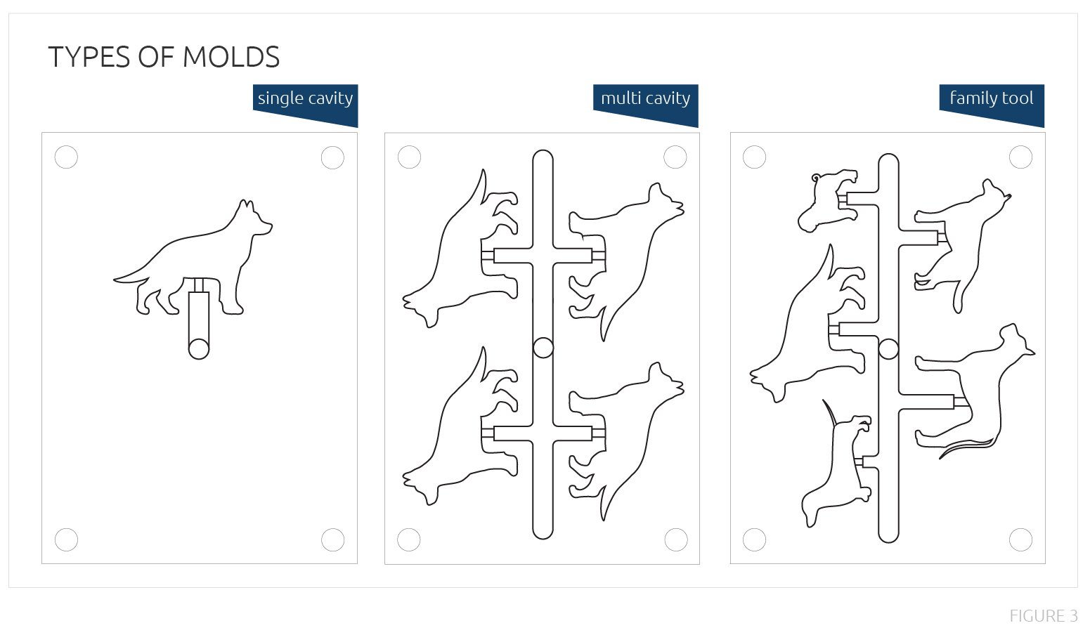
Single Cavity
Single cavity tools produce one part at a time; perfect for low volume programs or large parts.
Multi-Cavity
Multi-cavity tools produce many of the same molded part in one cycle and are ideal for high-volume production, reducing manufacturing time and labor.
Family
Family tools produce multiple different parts in one cycle. However, because of the varying sizes and features of the parts, this mold should be reserved for low quality, non-critical, non cosmetic parts.
Side Actions
Depending on the complexity of your part and whether or not features can be designed out of the part, the tool designer may need to add a side action. Side actions are special features that are designed into a mold to help achieve tricky part features. These add cost and increase mold complexity and maintenance.
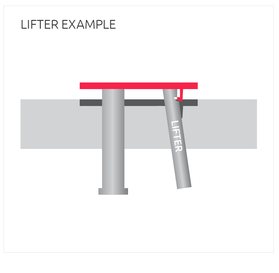
Lifters
Lifters release internal undercuts. Once the part has cooled, the lifter pushes up at an angle to release the undercut.
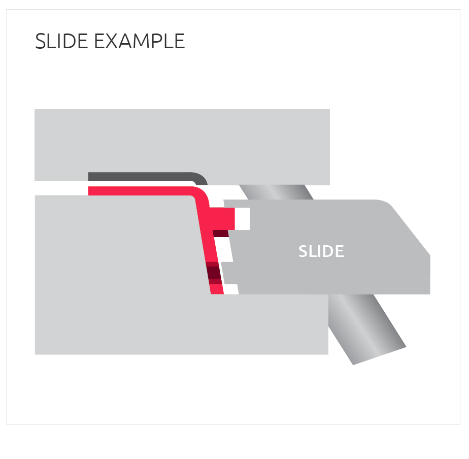
Slides
Slides release external undercuts. The part is molded around the features cut into the slide. Once cooled, the slide is pulled away from the part by an angled pin attached to the core side of the mold.
Collapsible Core
Collapsible cores release circular undercuts and can be used for threaded features. The part is molded around the core and once cooled, the core collapses to allow the part to be removed from the mold.
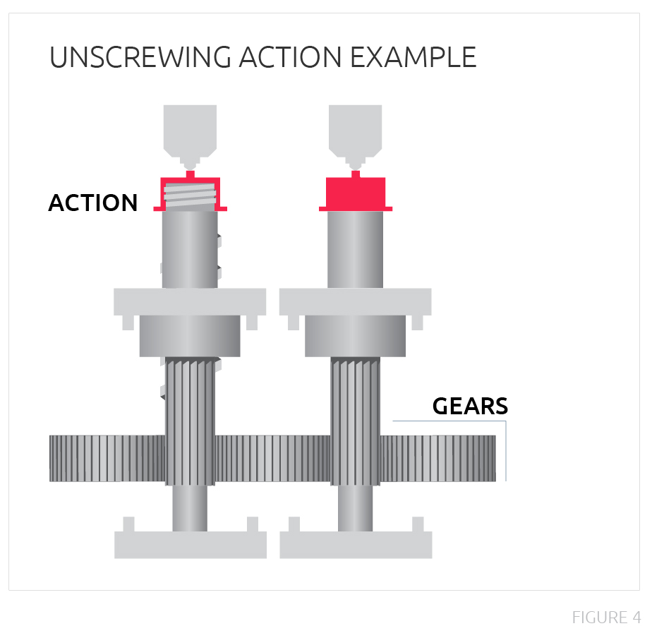
Unscrewing Action
Unscrewing actions are used for threaded features. The material is molded around the unscrewing action and once cooled, the action turns and unscrews itself from the part.
Specialty Injection Molding
Structural Foam
Structural foam molding is a process that uses the part material mixed with a foaming agent, which turns into gas as it enters the mold. Less material than needed to fill the cavity is injected into the mold and the gas bubbles expand until it fills the cavity. This creates a cellular structure within the part. Due to the unpredictable nature of the gas, structural foam parts may not be aesthetically pleasing. Structural foam parts have an uneven surface color; you can visibly see tints and shades of the chosen color in a swirl-like pattern.
This process is great for large, thick parts that are structurally sound, light weight, and are less likely to warp. Structural foam molding uses less material and a lower tonnage press.
Overmolding
Overmolding is the process of molding plastic onto plastic or metal components. A part is engineered to fit into a steel mold to allow plastic to be formed around the part, creating a strong bond between the part and the overmolded plastic and eliminating the need for assembly.
Insert Molding
Inserts are loaded into the mold manually or by a robot. The mold then closes and plastic material flows around the inserts. The mold must be designed to accommodate the required inserts, but this process alleviates the need for labor intensive assembly and creates a stronger bond between the part and its inserts.
Two-Shot Molding
Two-shot molding is a process to achieve plastic on plastic overmolding results. As its name suggests, the completed molded part is created with two shots from the injection molding machine. The first shot creates the base, typically rigid, plastic component. The second shot overmolds the commonly flexible plastic onto the first shot plastic.
Materials
Commodity Grade
Commodity grade resins are your most common injection molding materials. They tend to be less expensive and are easier to process, making them great for a wide variety of consumers goods.
Engineering Grade
Engineering grade resins are a step above commodity grade plastics and are produced with specific properties in mind such as high heat resistance, chemical resistance, or strength. Several companies who produce materials for injection molding design custom resins that are formulated to meet specific application requirements.
Virgin vs Regrind
Virgin material is brand new material that has not been previously used. Regrind is material that has already been run through the machine but can be ground down and reused in a blend with virgin material. The benefits of using regrind include cost and waste reduction.
Regrind is not a viable option for everyone. Blending regrind and virgin material changes its melting temperature and viscosity, which can greatly affect the molding process.
Conclusion
Understanding the basics of injection molding is incredibly helpful when you are ready to introduce a new product to the market, but you should also discuss your program with a Design for Manufacturability (DFM) engineer before moving too far into the tooling and production process. These experts provide an invaluable perspective on part and tool design, material selection, and cost avoidance.
About Cadrex
Cadrex is one of the largest manufacturing partners in North America, with 20 facilities located in nine states and Mexico. As a leading custom mechanical solutions provider for the most innovative companies in the world today, we offer a unique breadth of capabilities and technical expertise that allow us to rapidly bring customer programs from concept to scale. In addition, our decades of specialized experience designing and manufacturing for information communication technology, warehouse automation & robotics, kiosk & gaming, aerospace & defense, renewable energy & electrical infrastructure, and medical sectors make us a trusted partner in our customer's supply chain.